


DIY kits
This page contains some important info about DIY kits. We're considering that you have necessary skills to solder and setup computer and understand basic principles of its operation.
Components
All components in the kit are from official suppliers only, there is no ebay items except some special cases.
Compiling the kit we're trying to make components visibly distinct: using capacitors and resistor with different colors (e.g. 100u capacitors usually are blue while others are black etc.). But it is not strict rule, we are limited by the supplier.
All MCU are pre-programmed with bootloaders and all fuses are set, so you need only UART adapter to upload firmware, no need to have AVR ISP programmer.
Only shielded sockets are used! No "noname", usually that are from KLS or Connfly.
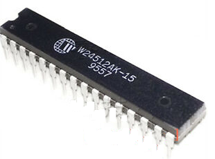
Critical point of the device is SRAM chip W24512AK-15. Unfortunately they are available only via ebay and all of them are used. No choice. Chips comping from the sellers are alive but most of them doesn't fit timing requirements. We test all of them and put in the kits only good one. For the 10 pcs arrived we get just 1-2 that works fine. So our advise to buy RAM chips for spare parts for the future.
All quartz resonators are from Geyer and we hope that there will be no problems with them. Clock quartz is relatively accurate but for better accuracy you can play with additional loading capacitors, PCB has place for them.
All components may be DIP, but in the kit we put some elements in SMD 0805 body: 49.9 ohm (R23-R26) and 2.32 k (R14) resistors that are not available in DIP form. If you hardly hate SMDs please tell that when ordering and we'll put DIP resistors as close as possible to the specification. LD1117 voltage converter is included in SOT body, but it is mounted like any standard TH component, don't worry about that.
Addons
Together with the kit you may order some additional components.
SD holder options: by default the kit has simple holder without push-push feature, if you want more comfortable holder with this option please note it, PCB supports both types of the holders.
SD card with programs: standard SD card 128Mb with the set of some basic programs. It can be used for the first run and basic learning but please do not expect that this card contains all available programs and is self-updating. In any case later or earlier you'll need to upgrade it - please refer to User's guide how to do it.
UART USB adapter: standard adapter from the computer shop. We can't guarantee that it will something specific, usually it is PL2303HX chip based. Please browse the Internet if you have a problem with drivers.
PS/2 keyboard and mouse: these devices are too big to be sent and no sense for that: till now they can be easily found in the computer shops or at ebay.com. But if you have too much money and want one from the author's hands please send a request by email, we will buy and send them to you.
Packing
All components are packed into the small plastic bags, chips are placed on the protective foaming substrate. As a rule components are distributed so to avoid soldering errors, e.g. capacitors 22p and 100n are located in different bags. All resistors are located in the separate bugs and individually marked.
"Big" components are covered with the protective bubble film. PCB is protected by special protective envelope.
The whole kit is put into the rigid carton box, empty space is filled with the filler.
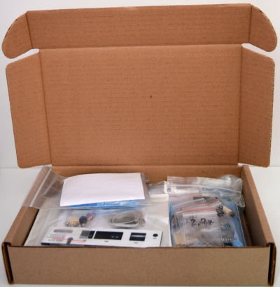
Back panel and PCB have barcode identification, please don't remove that and provide us any of these IDs when asking any question.
Packaging box is shown only for reference, other safe packing may be used.
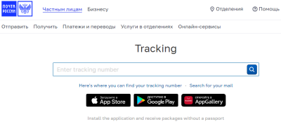
Delivering
Standard air delivering via Russian post (or EMS) with tracking is guaranteed. If you need cheaper or more comfortable option please contact us. Any option including courier service and personal delivering by the creator are available :)
We're trying to dispatch orders next day after ordering but sometimes it may take more time, please be patient and trust us. Be sure that your order will be sent ASAP.
Standard parcel is approx 450-550 g weight.
Delivering takes about 5-10 days to the destination country and after that everything depends on the custom clearance procedure. It may be 1-2 days (for US for example) or 3-5 weeks (Romania, Germany, ...). Usually delivering totally takes 2-3 weeks. EMS shows the same speed and we've excluded this option. But if you want to use EMS, DHL and other services you may pay them directly, the stock is located in Moscow region (Russia). Local delivering (Russia) takes usually 5-7 days.
Please send me a message on the package arrival - I'll send you latest firmware and instructions.
Assembling
Before the assembling please contact us by email to get latest schematic and instructions! There is nothing in the kit!
Assembling has no special requirements and can be done by anyone having basic soldering skill. Actual schematic and elements placement you'll receive by email. Usually basic version takes approximately 2 hours, it has less than 100 components.
Please note that all MCU are pre-programmed with bootloaders and you needn't AVR ISP programmer.
To understand the assembling procedures please refer to the video-lesson that can be found here: www.youtube.com/watch?v=P-KTUIjS7Yo.
Suggester assembling order:
- start with small size components: SMD resistors (if any), SDC holder, diodes, resistors, small capacitors, quartz resonators;
- after that install all IC sockets, but do not install chips into them;
- mount other ICs;
- install capacitors and other "big" components excluding the fuse.
The kit contains IC sockets only for significant chips: MCUs, RAM, RTC, Ethernet controller. All other chips are soldering without sockets. But if you want you can add it yourself.
In the kit you may find 2 MiniDIN sockets: 8pin and 6pin. The PCB allows to install any of them, but:
- MD6 allows direct keyboard connection or using keyboard and GPIO via the standard PS/2 keyboard/mouse splitter. RS-232 in this case will be lost or you can use 3.5mm socket on the back panel for it cutting the tracks on the PCB and wiring contact pads, audio output in real life has no practical sense.
- MD8 has all interfaces on it but you'll need to solder external adapter MD8M to MD6F for the keyboard, DB9 for the RS-232 and any 4-pin socket for GPIO adapter or LPT adapter (will be published soon). I'll send you wiring diagram for it.
The decision here is on your side. There is no problem to build an adapter, you'll need just two standard connectors and some wires. Standard version is always delivered with the MD6F socket, MAX may has both except the case when MPS adapter is ordered, in this case only MD8F socket in included.
In the there are 7 pins of the header connector. They should be used as follows (marked on the picture below):
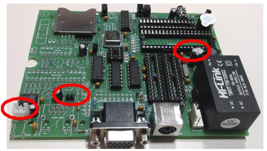
- speaker connector - 2 pins;
- 5v external power supply - 2 pins;
- in-system socket for the firmware uploading - 3 pins.
Some important notes:
- when installing HU-4 socket for the power cord please remove two central pins;
- don't forget to put wire protective rubber grommet on the cord;
- all places with the high voltage including pads and components leads MUST be protected with the silicone glue to avoid electrical shock.
Some comments to the MAX version only:
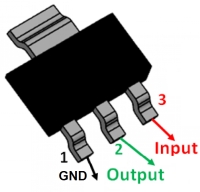
- LD1117 is mounted like standard TH component, despite it is in the SMD body, its pinout is on the figure (thanks to Martin from Canada for it);
- there are "two" R14 on the PCB, but they are parallel and you should use any position for the 2.32k resistor. If you're using TH resistors please select pair of values that give in the parallel the value close to the 2.32k as close as possible;
- if you don't want to deal with SMD components please install R23-R26 51 ohm TH resistors, please tell us in advance that you prefer this option.
Onboard RTC has some peculiarities:
- RTC backup battery is CR1632, it is not included into the kit, please take care about it;
- DS1305 chip allows to use rechargeable 3.2V battery, PCB also allows to use this option: instead of the battery holder please install 2-pin socket that shares the same space, any 2.54mm pitch socket can be used. But to use it you must cut the route on the PCB between pins pads. Also please note that firmware doesn't support charging, you will need re-init the chip following the datasheet instructions. How to do that please refer to "Working with SPI bus" section in the manual.
After all components except fuse are installed test the board:
- plug-in it into the AC power line and check voltage on the exit of the AC/DC converter, it must be 5V, plug-off the plug;
- using external power supply +5V 1A unit feed the PCB via the 2-pin +5V/GND socket near the LAN controller and check that consumption is less than 150 mA.
If everything is fine, install the fuse and insert ICs into sockets taking into account that VGA MCU is marked with the white pixel. Assembling is done!
If you are assembling MAX version it is advised to assemble first standard one, check everything and after it install other components.
One final note concerning the sound:
- "ideal" internal speaker is not found yet: it is either complicated to mount or sound quality is not good enough. We're trying various options. So if the speaker in the kit will not be loud enough for you please just replace it with any 8ohm 1W speaker. In the kit "mini" speakers are used because they can be mounted without any special tools;
- the buzzer on the board is really loud so if you don't like it just do not remove the protective seal.
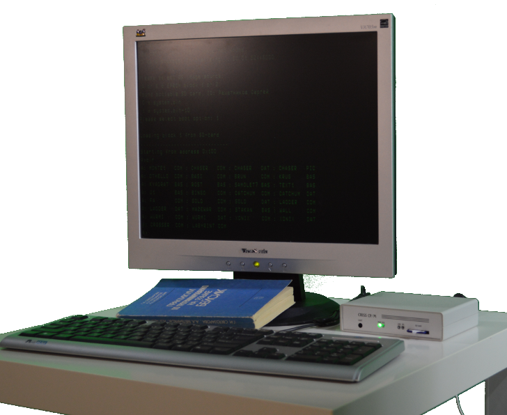
Startting new device
After assembling is done and you've checked everything and sure that there are no issues you can mount it into the enclosure. It is recommended to place PCB together with the panels. But don't put the cover - connectors for the firmware uploading are on the PCB only!
Power-up you just born CRISS CP/M. If there were no errors in the assembling it will wait firmware uploading: SYS led lights up fo 1s, after 1s you will hear a игяяук beep and everything will restart. It means that everything is fine and you can start with the firmware uploading.
Thank you to Mutsuo Gamo from Japan for this video!
Switch off the computer, connect keyboard and VGA monitor.
To upload firmware you need to do the following steps:
- download from the www.criss.fun website special program for the firmware uploading and start-up firmware set and unpack it;
- using the UART-USB adapter (not RS-232!) connect to the internal socket and note COM-port number;
- connect the adapter to the internal system programming connector, observing the order of connection (from left to right pins Rx, Tx, GND of the adapter), usually white - green - black, the red wire of the adapter must be securely isolated;
- run the bat-file of the installation package with the number of the COM-port as a parameter - the program will start and go into standby mode;
- turn on your computer - boot-up will start automatically accompanied by SYS indicator light and audible signals.
When the installation is complete, power off the computer, disconnect the adapter, replace the top cover and fasten it with the mounting screws.
Please refer to Firmware updates section of the site for more details.
Cables and connectors
This chapter is moved to the Technical Reference.
Troubleshooting
Almost all devices if they are assembled correctly start from the first run, but if you have encountered a problems please refer to this section.
Before starting please remove from the sockets all components that are optional: RTC, EEPROM, Ethernet controller. Also please re-check the assembling and direction of the IMCs in the sockets.
Step 1: on the PCB there are some control points, please check that:
- +5V power is stable and is in the range 4.9-5.2V;
- +3.3V SD-card power is stable and is in the range 3.2-3.4V;
- 25.175 MHz VGA clock presents and has at least 3.5V amplitude;
- 20 MHz main clock presents and has at least 1.5V amplitude.
Step 2: check that after power the standard behavior is observed: SYS led flashes and tone beep is produced. It means that main CPU works fine and is waiting for the firmware uploading. Important: all MCU are coming pre-programmed with bootloaders only, you'll need to upload the firmware, please refer the manual how to do it.
If main CPU doesn't work in this way please find the AVR programmer and check that fuse-bits are set and bootloaders are uploaded. It is very not probable that it will be the case but please check it to be sure.
Step 3: Check the firmware uploading process:
- if it doesn't start at all please check your UART adapter and pings assignment, usually the problem is here;
- if the process is very slow and unstable try to switch off your virus protection, stop all services that could prevent real-time processing like Dropbox etc. After the uploading has started minimize you cmd window to the tray. These should help. If the uploading was interrupted don't worry and restart it.
Step 4: Re-feed your device and check that VGA controller works and welcome screen appears. If now check signals on the RESET pin of the ATTINY13 MCU (DD11) and the R pin (12) of the DD10 counter. If they are high and low respectively please check VS and HS generation on the DD11 pins: if no sync signal is observed and the clock on the pin2 of DD11 is ok, please check DD1 that the firmware and fuses using an AVR programmer. If sync signal is fine please check internal circuits, cables and connectors.
Check the output pin 13 of the DD9 that video signal is generating. If there is no video signal check that VGA MCU is enabled and pin 1 DD8 is high. Check the clock at pin 9 of the DD8. If everything is correct please check DD8 fuses and firmware using the AVR programmer.
Step 5. Check that welcome screen has appeared and keyboard works properly. On the power on all leds on the keyboard must flash it means that it is powered. If the adapter (if any) is soldered correctly please check PS/2 signals on the pins 4, 6 of DD5, check internal circuits. If everything is correct please check DD5 fuses and firmware using the AVR programmer.
Step 6. Start you computer without SD card: it should show the initial screen, pressing Enter should lead to re-checking the SD what is accompanied with SD led flash. Insert prepared SD card and press Enter: SD should be detected and the bootload option(s) should appear. If now please check SD-holder, 3.3V SD power circuits, try to use another SD card (the smaller the better, 128Mb is advised).
Some SD cards are not compatible with CRISS CP/M and if you see unusual characters on the screen most probably it is related with this reason. CRISS CP/M has simplified diode-based level translation and in some special cases it leads to the card in-compatibility. Just use another SD-card from the another manufacturer.
Step 7: If after the booting you don't see A> prompt and the cursor is located in the first column of the "Starting from ..." message most probably it is related with the SD image or bad SRAM chip. We're testing 100% of SRAM chips but unfortunately sometimes this problem appear. Please rewrite you SD card using the image from the web site, if it will not help please replace SRAM chip. But please take into account that approx 1 for 3-5 pcs passes timing requirements.
If nothing had helped please contact us by email attaching:
- detailed description of the problem;
- photos pf the assembled PCB from the both sides in high resolution;
- video what is happening.
Don't worry: we will assist you and any problem will be solved.